Building Wi-Fi Buttons with ESP8266
Four years ago, I wrote about using Amazon Dash buttons as simple hackable Wi-Fi buttons. It’s pretty cool to order pizza, turn on a light, send a tweet, or even run a custom script at the press of a physical button. But I recently tried to use one of my dash buttons and couldn’t get it to work. I then learned that Amazon has completely killed off the dash button product, and even sent out a firmware update that permanently disables existing buttons. This inspired me to build my own Wi-Fi buttons using ESP8266 microcontrollers.
What makes a good Wi-Fi button?
The great thing about building something yourself is you can make it exactly how you want. I thought about the things I wanted in a Wi-Fi button (and several annoyances I had with the Amazon Dash button) and came up with a list of goals for this project.
- Inexpensive. I wanted the finished product to be relatively close to the $4.99 price point of the dash button.
- Fully hackable. I wanted the Wi-Fi button to be able to run custom code directly and not have to rely on an additional server running on the same local network (dash button requires this).
- No dependencies that I don’t fully control. I didn’t want to depend on free cloud services (like IFTT) that may eventually expire or get discontinued when the company gets acquired or changes its strategy.
- Fast. The Amazon dash button took about 10-15 seconds to wake up and make a web request after being pressed. I wanted a button where I could see the result in under 5 seconds.
- Long battery life. Similar to the dash button, I wanted years of battery life so I didn’t have to worry about charging.
- Looks nice. Amazon Dash buttons have a cheap, plastic look. I wanted something that actually looked good enough to sit on my desk next to my computer or in other visible places in my house.
Hardware
If I was going to build something super cheap that also had good battery life, I knew I’d have to consider a microcontroller with onboard Wi-Fi. I’d heard about the ESP8266 before and it seemed like a perfect fit for what I was trying to do. ESP8266 is a family of low-cost Wi-Fi microcontrollers made by the Chinese company Espressif Systems. The ESP-01 was the first popular Wi-Fi chip they produced back in 2014 and it has a rock-bottom price, low power consumption, and it’s remarkably small. Similar to the Raspberry Pi, there is a large community of makers using the ESP8266 chips and many using the ESP-01 module specifically.
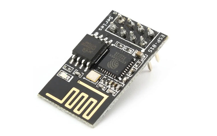
I eventually selected the ESP-01S (a derivative of the ESP-01 module) because it has more flash memory and doesn’t have an always-on power LED like the ESP-01. This saved me the step of having to remove the LED to prevent it from draining the battery.
Below is my final parts list:
- ESP8266 ESP-01S Microcontroller 4x - $3.50 each
- ESP-01S USB Programmer - $8.99 each - Not required but makes it much easier to program with Arduino. It has a switch to go from programming mode (PROG) to serial mode (UART).
- ESP01 Breakout board 5x - $1.40 each - Not required but makes it much easier to prototype with on a breadboard.
- 3.7V 1000mAh Battery 4x - $5.70 each
- 1.25 mm JST 2 Pin Male/Female Connector 20x - $0.35 each - I got these so I can easily disconnect the battery for charging.
- Button Option 1: Push Button Momentary Switch - $1.00 each
- Button Option 2: Sanwa Arcade Button - $2.50 each
The total cost comes to about $12 per button (not including the USB programmer). You could also save a lot by going through Ali Express (I’ve heard ElectronicFans is a good store for this), but I prefer the convenience of Amazon.
Setting up the ESP8266 for Programming
Being new to Arduino/ESP8266, I had to overcome some initial hurdles. I wish I had read (or at least skimmed) this guide before diving in. You can also find it in PDF form here.
To connect the module to your computer, you need to plug the ESP-01S into a USB programmer (overhanging towards the USB connector) and flip the switch to PROG beforehand. Make sure you aren’t using a USB hub. The safest bet is to use a primary power+data USB port directly on your computer.
You’ll then need to identify the computer name of the port you connected to. This can be done via Device Manager on Windows or directly via the Arduino > Tools > Port menu on Mac. On Windows, the USB ports start with “COM”, and on Mac, they start with “/dev/tty”.
Next, you should update the ESP8266 firmware. Many features (like using Deep Sleep to conserve battery) will not work properly without newer firmware. I used this updater on Windows and it worked great (it’s all in Chinese though). You can also use the official flash download tool here, but it requires many more steps. Make sure you select the correct USB port when you flash the firmware.
Finally, you can download/install the Arduino IDE and program the module. Make sure to plug in the USB programmer in PROG mode with the Arduino IDE open, and you should see it automatically detect the correct port.
Writing the Arduino Sketch
I went through several iterations of Arduino “sketch” and finally landed on this version. The entirety of the code exists in the void setup() function because it’s intended to only run once. The module is “reset” every time the button is pressed (more on that later).
The sketch is based on the Arduino WiFiClient example but with one major caveat. The WiFiClient example code does not define any headers in the GET request. This might work if you are running a local webserver and connecting to it only by IP address, but in general, this doesn’t work on the Internet.
Why? Most web servers on the Internet host multiple websites or web apps on the same IP address. To accomplish this, they rely on a “Host” header on the incoming request that tells the server which website/web app (also called “virtual host”) should process the request. When requests come in without a “Host” header, many web servers will be unable to process the request and will simply return an HTTP 400 or HTTP 500 error. This is why the HTTP 1.1 spec requires the “Host” header to be passed in all requests.
It took me a bit of digging to discover this, but I was able to modify the example to work properly by passing the required headers as shown below:
// Make GET Request with Headers
if (client.connected() ) {
   client.println((String)"GET /?device_id=" + device_id + " HTTP/1.0");
   client.println((String)"Host: " + host);
   client.println("Connection: keep-alive");
   client.println("Cache-Control: max-age=0");
   client.println("User-Agent: Mozilla/5.0 (X11; Linux x86_64) AppleWebKit/537.36 (KHTML, like Gecko)");
   client.println("Accept-Language: en-US,en;q=0.9");
   client.println();
}
It’s important to note that you can fully test your code using the USB Programmer itself. Just unplug it, flip the switch to “UART” and plug it back in. Now you can open the Serial Monitor in the Arduino IDE (Ctrl + Shift + M on Windows) and watch it log things as the code runs. For this sketch, you’ll have to unplug/replug the USB to test each time, but I was able to get consistent results this way.
A Simple Serverless Web Endpoint on AWS
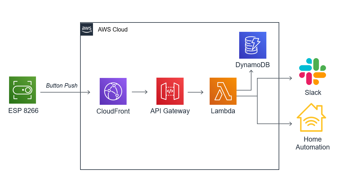
One of my goals was to avoid free cloud services, so I decided to create a simple serverless API on AWS for this. I decided to use AWS Lambda as the “brains” behind each of these Wi-Fi buttons. I set up a simple Lambda and then configured AWS API Gateway as a web API that would trigger my Lambda function.
I didn’t want to worry about expiring SSL Certificates on my ESP-01 modules, so I decided to go with a basic HTTP approach. However, API Gateway is HTTPS only. This meant I needed to create a CloudFront distribution sitting in front of API Gateway that would accept HTTP and forward those requests to my API. I made sure to set all the caching TTLs to 0 on CloudFront and enabled a behavior for forwarding URL query strings to the origin. This way I could pass a unique “Device ID” for each button in the query string to my Lambda and trigger different actions based on which button was pressed, all with a single Lambda function.
I had to create the proper IAM roles but I was able to get the API up-and-running quickly and began triggering it from my ESP-01S. I configured my Lambda function to notify me on Slack each time a button was pressed and created a DynamoDB table that would keep a historical record of all button presses. My AWS setup looks like this:
Wiring Everything Up
I don’t have much experience with building circuits, but I found a really good video that helped me figure it out. I wired up one of the button terminals to ESP-01 Ground (“GRD”) and the negative terminal on the battery. Then, I wired the other button terminal to Reset (“RST”). Lastly, I connected the VCC and CHPD terminal on the ESP-01 to the positive terminal on the battery.
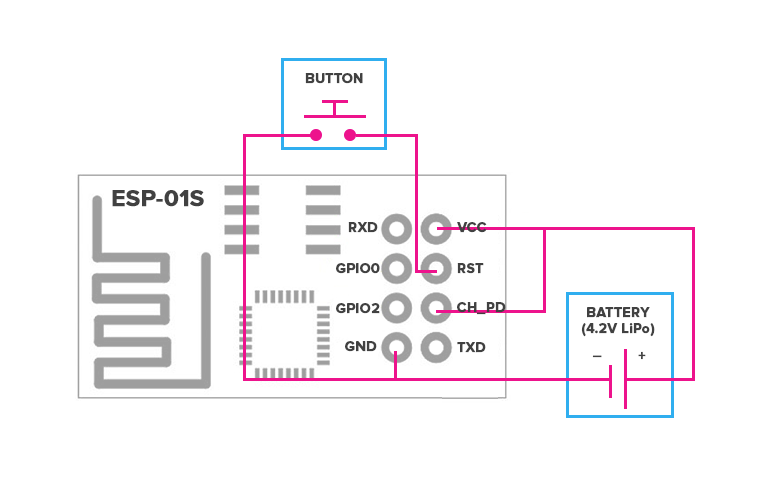
It works by having the “Normally Open” button sitting between the reset and ground pin on the module. When the button is pressed, the circuit is completed (“closed”) between these pins and the module resets itself, immediately running the setup() function before going back to sleep.
Also, I decided to wire up the buttons using breadboard adapters. This way I could easily detach the ESP-01S module and reprogram if necessary without having to desolder.
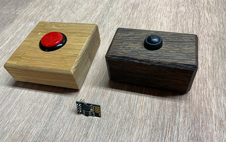
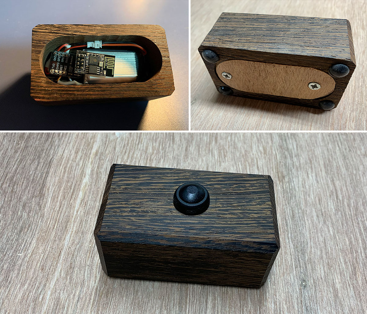
Building Button Enclosures
Many people 3D print enclosures for their electronics projects, but sadly I don’t have a 3D printer (yet). I do have woodworking tools though so I figured I could build some good looking enclosures out of blocks of wood. First, I cut a simple block to size and routed the edges using a 45-degree chamfer bit. Then used my drill press with a Forstner bit to drill out the inside of the block to make room for the ESP8266 module and battery. I drilled a hole on top for a button and hot glued it in from the inside. Finally, I created a backing plate out of 1/8 inch plywood to cover the bottom, attached it with screws, and added some sticky rubber feet to them keep the button from sliding.
Conclusion
So far, I’m pretty impressed with these Wi-Fi buttons. After pressing the button, I see a message showing up in Slack within 3-5 seconds. Also, in deep sleep, it consumes only about 50 microamps (µA) which gives the 1000 milliamp-hour (mAh) battery about 2 years of runtime. That’s pretty awesome!
I also discovered that this setup works well for other applications too. I bought some reed switches and they work perfectly in place of buttons without changing the wiring at all. This means you can use this for triggering an action based on the opening/closing of something, like automatically turning on a smart outlet when your garage door opens.
I’ve just scratched the surface of what these ESP8266 modules can do so I’m excited to keep building and learning. This definitely won’t be my last ESP8266 project!